Lego Coding
Disclaimer:
I neither work for nor am affiliated in any way with the
"Lego Group ®". Although I am a member of
an "RLUG" (Registered Lego User Group), this
entire website expresses my own personal experiences and
statements.
"Coding" is simply the process of creating a list of instructions to be performed by a computerized device, in this case it applies to Lego devices such as hubs, motors, sensors, and lights. The actual coding is done via an app on a tablet, laptop, or cell phone, which sends commands to a Lego Hub via Bluetooth.
The fact that the Boost and Powered Up apps both allow for custom coding
is awesome. The fact that Lego itself has very little public documentation
for the specifications of the coding is not so awesome. Lego has a very
short page on their website which lists the Boost and Powered Up code
blocks with little extra useful information for usage of the apps. This is at:
Boost blocks
Powered Up blocks
This document focuses on my PoweredUp app because it allows for creation of custom code. Other Lego apps or even different versions of the PoweredUp app may vary from the information below. But hopefully this will give you the knowledge to get a handle on how it works.
PoweredUp app overview:
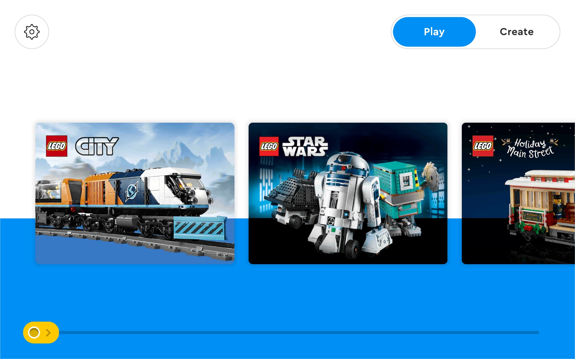
Once you download and install a Lego app on your device, you can launch it to start the play experience. This is the opening screen for my PoweredUp app.
In the top left corner is the "Settings" button. This allows you to set general preferences for the app. This screen allows you to scroll through specific sets for instructions on how to code it for operations.
At the top far left are two buttons: "PLAY" and "CREATE". Pressing the create button takes us to the custom coding section which this document is geared toward.
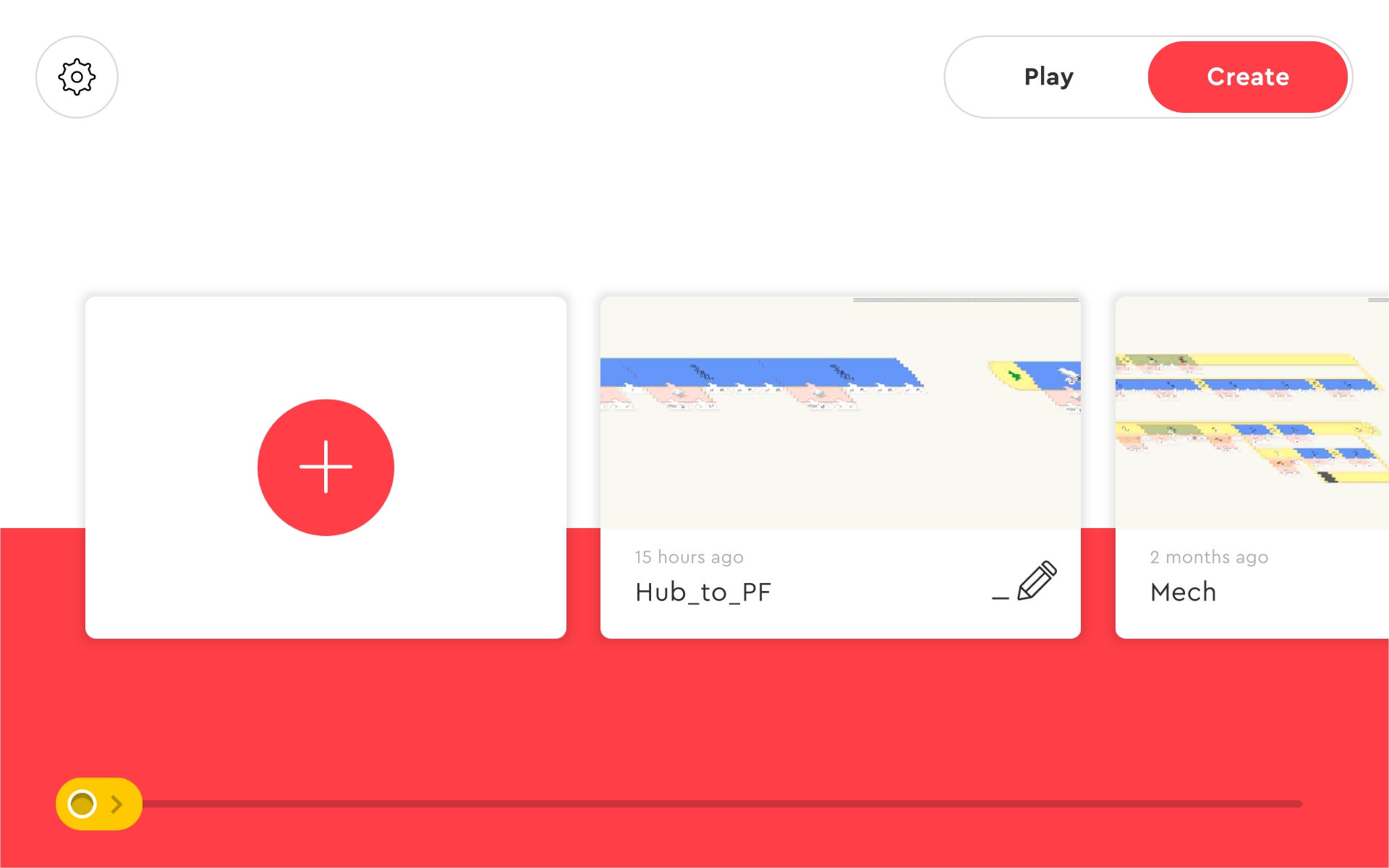
When you choose to create a "coding" project, you will get a "+" to add a new project and a list of all projects already created. Each project gets a unique name by default, but you can edit the name to whatever is desired.
Once a project is created, the code editor is shown. This is called the "Canvas". The canvas is where we build code segments and run them. As you work in the canvas, changes are stored so there is no need to manually save the work.
The layout is pretty simple. In the top left corner is a left arrow, which sends you back to the project list screen. Next to that is the Bluetooth symbol, which lets us manage which Lego hub(s) are used (more on that later). At top right is a controller icon, which lets you create remote control widgets. Next to that is a large green arrow, which is the button that starts all of the code segments to run. Near the lower right corner is a "..." symbol, which has settings which will be covered below.
Along the bottom are the actual code blocks that you can use to build code segments on the canvas. You select (press or click) the block and drag it into the canvas area where you want it. You build a code segment by placing a code block next to another. The app will 'join' them together if they are compatible. You can also 'unjoin' blocks by selecting it and dragging it away from the segment. The app tries to help us build, so it is well worth taking some time to experiment with how this works before you actually try to create a real code segment!
Just above the code blocks is the "block group list". This allows us to quickly select a specific group (flow, motor, lights, etc) of code blocks to be listed at the bottom. This is very useful for speeding up code creation!
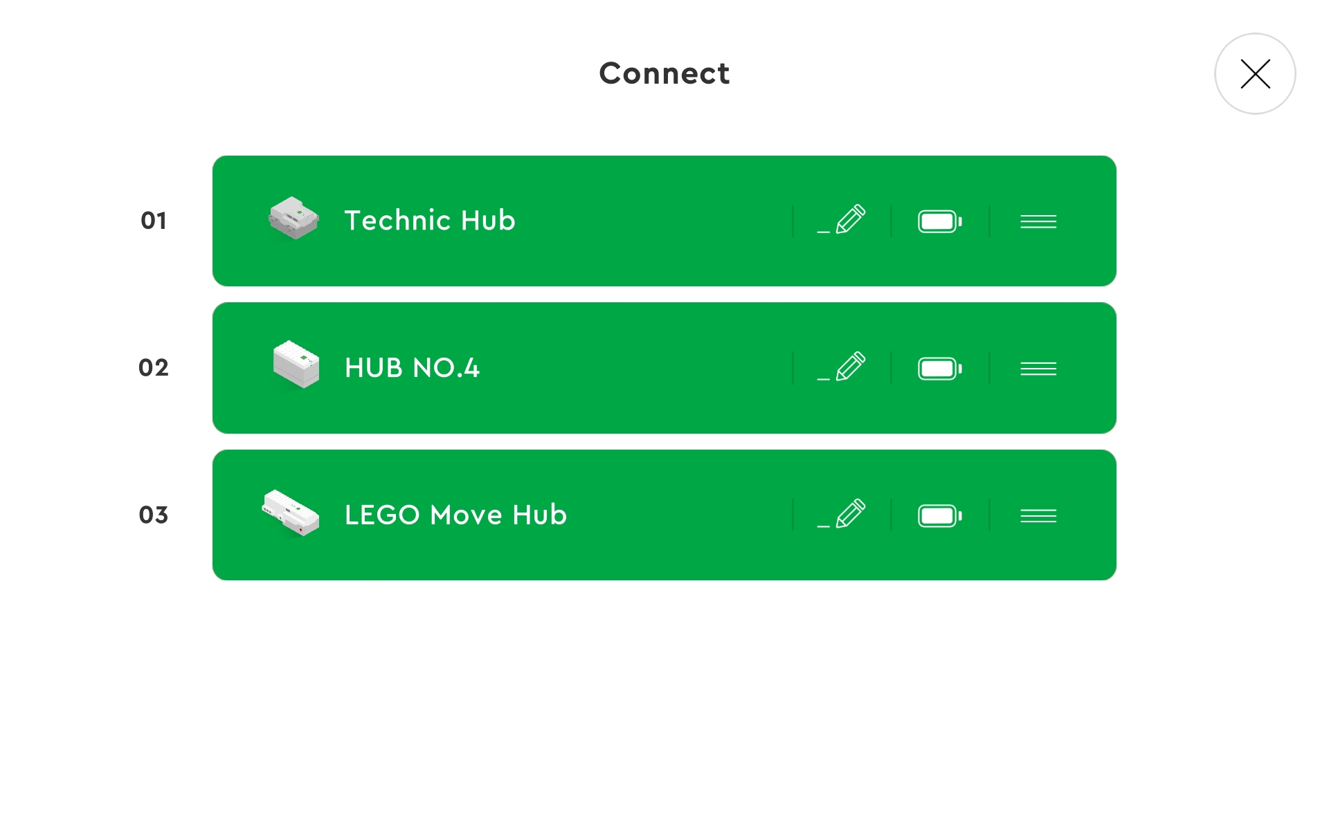
Pressing the "Bluetooth" button from the canvas screen leads you to the device management screen. This is where we can define what hubs or controllers our code will use. Each time we open the app there are no connected devices, so we have to add them. If your code includes references to specific device numbers, be sure to add those devices in the proper order!
To add a hub or contoller, simply press its power button. If all goes well, the app will connect with it and display it on screen. If the app allows for multiple devices, simply press the power button on the remaining units to add them. Note that the app may initially display only a gray box outline first, we have to tap that to authorize the connection.
Each device listed has a number, image, name, pencil, battery, and grab bar (three horizonal lines). The number is used in the code to identify a specific device. Use the pencil button to change the displayed name of a device. The amount of remaining battery power is shown, which is very useful. Pressing the grab bar allows us to move that device up/down in the list. Be advised that this changes its number, so code blocks may also need to be updated!
The only way I know of to remove a device from the list is to hold the device power button until it shuts off.
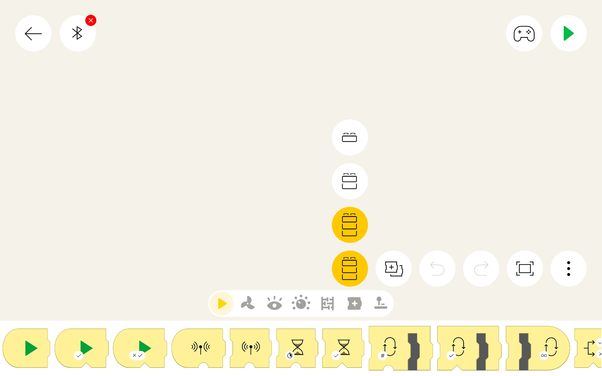
If you are using the PoweredUp app, you may have noticed the "..." options menu near the right lower screen (see image above). Sadly the icons are not described anywhere on the screen, so I will reveal what they are here. Working from left to right:
-
"Palette" (as shown above)
Selects the level of code blocks to display at the bottom of the app. Either beginner (top, 1 brick), medium (2 bricks, or advanced (bottom, 3 bricks). Fewer code blocks are shown when using beginner or medium levels, which may be helpful to those just starting to learn coding. -
"Copy"
Normally code blocks are just moved around the canvas. But when this is selected (highlighted), the original code blocks remain in place and a copy of them are moved. This is a great way to quickly build similar segments of code. -
"Undo"
Cancels the most recent change made to the canvas. Multiple undo actions may be limited based upon device memory or cache values. -
"Redo"
Puts back the most recent undo made to the canvas. Multiple redo actions may be limited based upon device memory or cache values. -
"Center"
Brings the code canvas back to the center of the screen. Will zoom out attempting to reveal the entire code if practical. This is especially useful when shifting work on a different code segment or when the code is moved off screen accidentally.
Coding:
There are a few guides done by third parties which are more complete and list more of the code blocks with some detail and example usage. But even those lack specific technical detail which Lego really should make public. Most notable missing items is the range for the color/distance sensor for accurate detection of color, light, motion, and distance recognition.
However being a GUI (Graphical User Interface) system, the icons do reveal basic usage hints and the input methods in the app also act as a guide to the range an option can have. Once you figure out what the icons and their attribute options graphics mean, you can better understand other icons too. So while initially a real Lego guide would be very useful to beginners, experience in the long run will eventually allow easier coding to occur.
Coding is done similar to putting a jigsaw puzzle together. The workspace is called a "CANVAS". You 'drag and drop' each piece (code block) around the canvas and join it to other code to make a horizontal program line (called a "SEGMENT"). The app guides this operation by adjusting the position of other code as needed and then 'locking' the piece in place when it is released. Code blocks lock together as their left or right edge indicates they can. Program segments must begin with some sort of 'start' block or they cannot be executed (run), this makes it possible to leave 'orphaned' code blocks on the canvas for easy access later on without them being run in the meantime.
Any options or input are connected to the cutouts on the bottom or top of a code block. "Reporter" blocks have a top part which make them connectable to the "options" of other code blocks. The status of a reporter block is thus used as the number or condition for that option.
Note the two different types of option connectors are either a triangle or a half circle. Only the same types will join together! Triangle shaped types indicate "logical" (true or false) values while half circle types indicate a value (number, hexidecimal, color, or reference).
All programs and subs MUST begin their segment with a 'start' block (rounded left side) in order to be executed. That program will stop (end) when it has no more blocks, encounters a 'stop' block, or all programs on the canvas are stopped. Note that other program segments can issue a 'stop other segments' order also.
Rather than create another third party guide, I thought it would be better to just show the basic icons and attribute patterns. Knowing the graphics allows you to understand a code block no matter which app is being used and if Lego creates new ones in the future. So the table below is a quick look at the groups and attributes:
|
PROGRAM EXECUTION: NOTICE: Activation of an individual code segment is done by clicking (touching) that segments 'START' block. However, ALL program segments on the canvas can be started by pressing the green arrow icon at the upper right of the app screen. This changes to a red square, which will stop ALL programs on the canvas when pressed. Yellow code blocks manage program execution including starting, looping, and stopping code. Code blocks with a rounded LEFT end mark the start of code segments. Code blocks with a rounded RIGHT end mark the end of code segments. Loop blocks run the enclosed code repeatedly before continuation of the remaining code in the program. |
|
|---|---|
|
|
This group of blocks START their attached program execution. The 'green arrow only' block starts the code segment when it is clicked (touched), while the other two green arrow blocks delay execution until their conditional option is met. The green flag block starts a sub program when its 'trigger' number is encountered in other program segments. |
|
|
The green flag block 'triggers' (runs) a sub program with that number. The hourglass blocks delay further commands until time (hourglass) or true condition (hourglass with ?). Red square blocks stop other sub program(s) execution and (if the right end is rounded) this code also. Notice that a '?' in the icon indicates that its operation depends on a true or false 'condition' to occur rather than a number. |
|
|
Loops allow for running code segments repeatedly, which is often useful in programs. Notice that a '?' in the icon indicates that its operation depends on a true or false 'condition' to occur rather than a number. The two 'branch' loop blocks allow two (upper and lower) code segments to be built within. The '?' branch runs the upper code when the condition is true and the lower code while false. The 'fork' branch runs both the upper and lower in unison, which allows for synchronized device control. |
|
HUB MANAGEMENT: Normally only one hub is used so we simply define the port of the hub where an accessory is. These code blocks allow us to specifically target a hub when multiple hubs are being used. This includes sending commands to Power Function receivers. Be advised that the order of multiple devices can change each time the app is reopened. So if you use these code blocks, insure that you activate hubs and devices in the same order as needed for your code. |
|
|
|
This is a special block which allows access to devices on hubs
other than the 'primary' hub. An app which allows for more than
one hub to be connected at a time (such as the Powered Up app)
has an ordered list of hubs, the first being the 'primary' (or
active) hub. Any ports used in code blocks reference the primary
hub ports. But this code block allows access to other hubs, with
its first option being the hub number (1 to #_of_hubs) and the
second option being the port on that hub.
The list of connected hubs is available by clicking (touching) the "Bluetooth" icon at the top left corner of the canvas. Be strongly advised that since you can change the hub order (using drag and drop), a hub number can change and thus make this code block reference unwanted devices. Also, if a hub is disconnected or the app is closed (which disconnects ALL hubs) a new list is generated as hubs are connected again. So while this code block is very useful, it has its drawbacks too! |
|
|
Note that there are at least two different icons for this
code block! The one shown here is not used in my PoweredUp app
but may be on other apps. Mine is a green block (light and sound)
and is shown in the example codes in the next section.
This is a special block which allows a distance/color sensor to send a command to a Power Functions IR receiver. Note that the sensor must first be placed in "IR mode" before it can be used in this way. See the example later in this document. The four options that need to be set are as follows:
Note that you cannot run simultaneous operations this way! It may also fail if a second operations is run immediately after another. Code tends to run faster than a device communication, so include at least a small delay between signal transmissions. |
|
SENSOR, HUB, APP DEVICE: Orange code blocks manage sensors and hub/app orientation. Here "DEVICE" means the device which is running the app. For the Boost sensors, distance is 0 (close) to 9 (far) or 10 (nothing is detected). Hub and device orientation is reported as numbers which are not in 'degrees of angle' units, are VERY sensitive, and may vary by hub or device. NOTICE: Experimentation is the best method to understand the behavior of YOUR specific setup! Hub and device orientation statistics might report different things for different devices. These numbers also change with even the smallest vibration. When using these in actual code it is usually best to build a 'range' conditional (if -reported value- is between -lowest value- and -highest value-) statement. Do a LOT of testing before making important decisions! |
|
|
|
Sensor detection can either start a program or have a program wait for the option selected to occur. The icon will have a color wheel (color detection), hand (distance detection), or grayscale bar (ambient light detection). The first option is always the hubs port (A, B, C, D) where the sensor is plugged into. The second option is the color (color detection) or distance (distance detection). Distance is 0 (close) to 9 (far) or 10 (nothing detected). |
|
|
Sensor reporter blocks are used to provide the program code block options with the value of the sensors detected color, distance, or light. They can also be used on the app canvas alone for a visual display of their current value. The only option is the hubs port (A, B, C, D) where the sensor is plugged into. |
|
|
Hub and device reporter blocks reveal the orientation of the hub or device running the app to the program code block options. They can also be used on the app canvas alone for a visual display of their current value. Options for hub orientation are the device and X, Y, or Z axis to report about. For the device running the app there are no options. Be advised that these values are VERY sensitive to even minor movement so it may be wiser to restrict options to a range of values instead of using the raw value reported. For example: "If device orientation is greater than 20 but less than 30, run the code". There is also a reporter block for the remote control, which reveals what button was pressed. For this you enter the channel (A or B), which matches the left and right side of the remote. This can be used in a comparison input option to control other code blocks. |
|
MOTORS: Green code blocks manage motors. Motors can be internal (Boost Hub) or external (wired to a port). There are several types of motors available with different properties. Some motors (called 'Tacho' motors for 'tachometer') can both seek to and report their speed and position. 'Linear' and 'Servo' motors are also available. Motor control seems to be fairly standard, although some options apply to different motor types. The first option is always the port of the motor (or motor pair). The speed (aka power) is a value from 0 (stopped) to 100 (full speed) with negative values usually for counter-clockwise movement and positive values for clockwise movement. Distance and position (when able) is a value between 0 (position of motor when connected) and 9999 (in rotation degrees (*)). Notice that 360* is one rotation, so a value of 9999* would be 27.775 rotations. Tacho motors can seek to a position using a positive or negative value as needed. Tacho motors can report their speed and position (via 'reporter' code blocks), which allows precision control AND reference of their current state. |
|
|
|
Notice the plain white motor face on the icons, this indicates no specific motor type, so these work for all motors (in theory). The first option is the port. Notice the 'meter' icon as the second option which is the speed (power) value. 'Float' (red square in icon) means that power is removed from the motor, although it can still move a bit via inertia. 'Stop' (red square with ! in icon) implies a brake is applied to actually stop the motor. |
|
|
These provide a way to control a pair of motors. The first option is the port of the two motors, such as AB (A and B) or AC (A and C). The second and third 'meter' options sets the speed (power) for the first and second motor respectively. This can be useful to synchronize or differentiat motors. The 'speed and steering' icon is useful to control two wheel vehicles (such as those using tracks like a tank or large construction vehicle). The second option (upward arrow) is for the speed (power) of both motors. The third option (steering wheel) controls what influence is applied to adjust the speed of one motor to cause a turning motion. The fourth option sets the directional difference between the motors. This action runs forever (note the rounded right edge), but constantly checks the second and third options for changes allowing for movement control. This is useful as single code block method to control a vehicle. |
|
|
Notice the curved red line on the motor face of these icons, which indicates they apply to the 'tacho' style motors. These are the basic 'Tacho' motor controls for operation. Note the 'up arrow' (in the icon by the second input) is for speed (power) and differs from the 'meter' style used in the row above. Speed is still 0-100 with negative values meaning counter-clockwise movement. The third option can be either a 'range' (circle with shading between two angle lines) or a 'position' (circle with just an angle line). The 'range' is used for distance to rotate while the 'position' is used to specify an exact position. Both use a value of 0-9999 degrees. Tacho motors can be reset to their 'start up' position simply seeking to position 0, which is VERY useful to put a motor used for steering back to its center position. |
|
|
Tacho 'reporter' blocks return the speed or position of a 'tacho' style motor. These can be used as options for comparison blocks or just alone on the canvas to give a visual indication of their value. |
|
|
More control over a tacho motor is allowed with these icons. First option is the motor port. 'Stop' (red square and ! in icon) stops and holds the motor, which implies a brake is used. The second option with a 'meter' sets the maximum power (speed) allowed (0-100) and stays in effect until changed again. The second option with an 'hourglass' is the time in seconds (with fractions allowed) for the action. The icon with the upward curved arrow is for 'acceleration' time while the icon with the downward curved arrow is for 'deceleration' time. These set the time desired before the motor gets to its full speed, often helpful to allow for smoother starts and stops. |
|
|
Tacho motor pair code blocks operate just like the single
motor versions except they work with a pair of motors.
Note the 'up arrow' (second and third options) is for speed
(power). The fourth option can be either an hourglass (sets
time in seconds) or a 'range' (sets distance in degrees).
There are a few other icons (varies by app) which offer other control options, but mostly the option symbols for them work as those described in this section so are not repeated here. |
|
LIGHT AND SOUND: Purple code blocks manage light and sound. The sound file block icons have a speaker at the lower left corner. These are different for each app so they are not included in this table. |
|
|
|
The intensity of an attached LED string can be controlled by the first block. Here the first option is the port and the '%' option is the percentage of intensity, 0 (off) to 100 (brightest). The status light color of the hub can be changed with the second or third block, with the port being the first option of both. The 'paintbrush' option allows a color to be choosen from a color picker menu. The three '%' options allow an RGB color value to be specified, using percentage (0-100) rather than an actual value (0-255). The sensor light color block also has a 'paintbrush' option with a color picker menu. |
|
VARIABLES AND MATH: White code blocks manage variables and math/numeric operations. Variables are used to store values for future reference. There are 'local' (box of folders icon) and 'global' (with a globe) variables. A local variable is only available to the code segment it is defined in, while a global variable is available throughout the canvas. A variable can only store ONE value at a time, but there are many variable names to choose from so this shouldn't be a problem. There are also a variety of math function and comparison operations available, which are mostly used to control the options of other code blocks. These typically accept two values for the comparison or operation. These can be numeric, the value of a 'reporter' block, a color picker value, or other appropriate value. |
|
|
|
Variable reporter blocks have just one option, which is for the variable name. Variable setter blocks have a second option for what value should be stored in it. Setting a value overwrites any value it previously had. |
|
|
These commonly used logical comparison blocks which return a 'true or false' value, used for code block options that have a similar 'triangle shaped' connector. These are called 'conditional' blocks because the value is based on if the condition is true or false. |
|
|
These 'conditional' blocks take on two 'conditional' options with the result being a 'conditional' value (true or false). "AND" returns true if BOTH options are true, otherwise it returns false. "OR" returns true if EITHER option is true, otherwise it returns false. |
|
|
These are simple math blocks which perform their operation on two numeric options and report the numeric result. |
|
|
The 'inversion' block simply inverts the option values positive/negative state and returns the result. Negative options (such as -5) are inverted to positive (5), while positive options (such as 7) are inverted to negative (-7). The 'maximum' and 'minimum' blocks compare the two options and return the result. So '3 max 7' would return 7 and '3 min 7' would return 3. |
|
|
The 'random' block returns a random value in the range of the
two numeric options (inclusive). The 'modulo' block returns
the modulus (remainder of a division operation) of the two
options. The 'ADV' block has a variety of advanced math
functions to choose from (first option) to work on the second
options value.
Math functions available may vary by app or be added to in the future. Not all math functions are listed above. |
Exploration of all the code blocks available in the app you use is a fun way to learn. Using the icons, symbols, color groups, and basic descriptions should allow you to figure out any unlisted blocks which are encountered. Think about what you want to do, think about what code blocks need to be used, experiment and test, retest and retry as needed, and then enjoy the successful result!
Examples:
This one is fairly complex, so I include it only as a challenge for those who want to figure out what it does. Below is the general description, so don't read it unless you need extra clues.
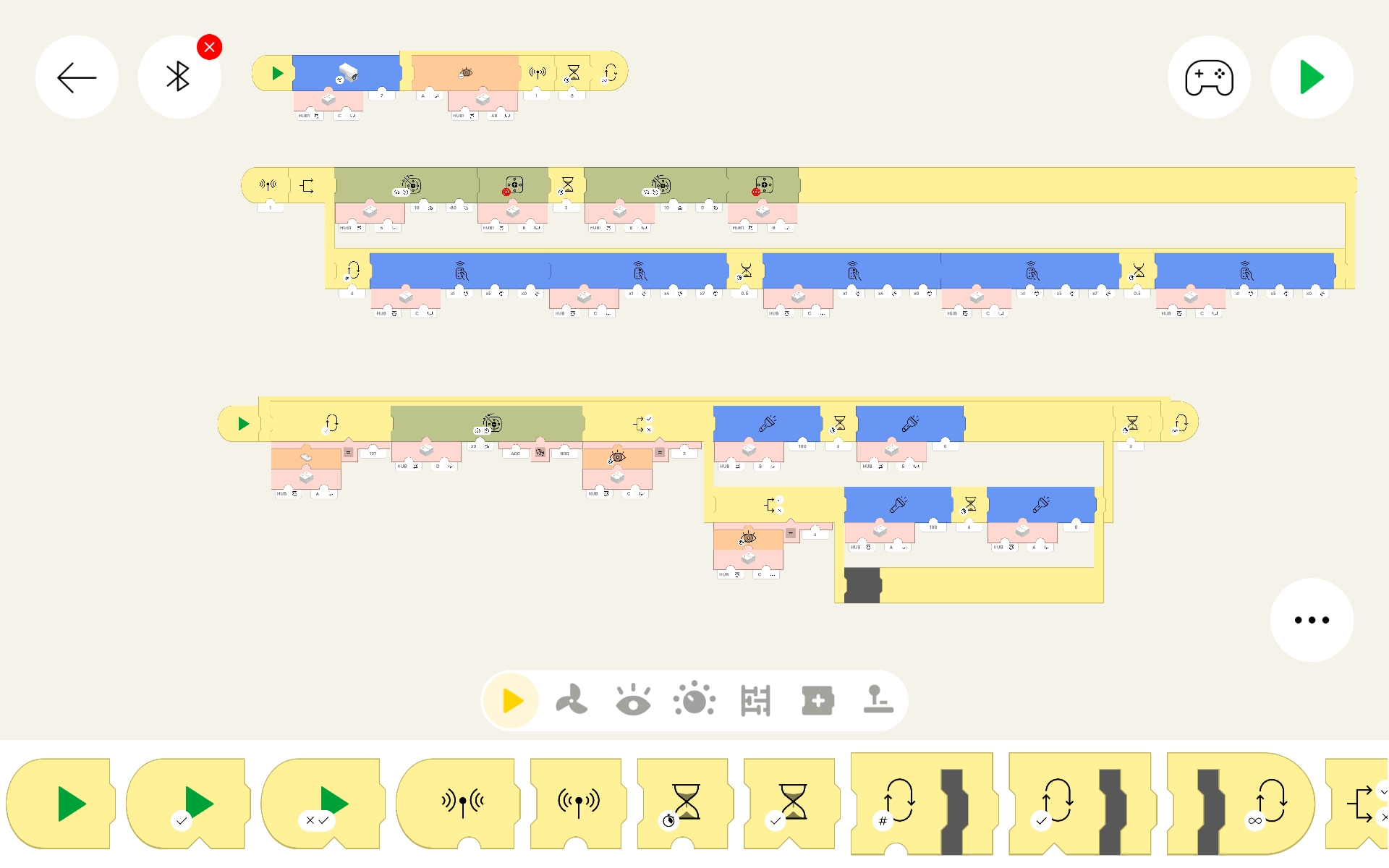
This is the code I used for my train display to operate a crossing guard gate and lights. One hub had the sensor to detect when a train was passing (approaching the crossing) and a motor to lower/raise the crossing guard gate. Another hub had only a sensor, which was used as an IR transmitter to a Power Functions receiver. The Power Functions unit ran the lights of the crossing gate, switching them on and off to simulate flashing. Each loop has a preset timing for operation, optionally another sensor could have been used to detect when the train left the crossing to lift the gate and stop the lights.
I include this because very few people I have talked with know that the PoweredUp devices can also control the old Power Functions units! Notice the code block for "IR to Power Functions" in the "Hub management" section of the code block table above. It has the details on setting up the block values.
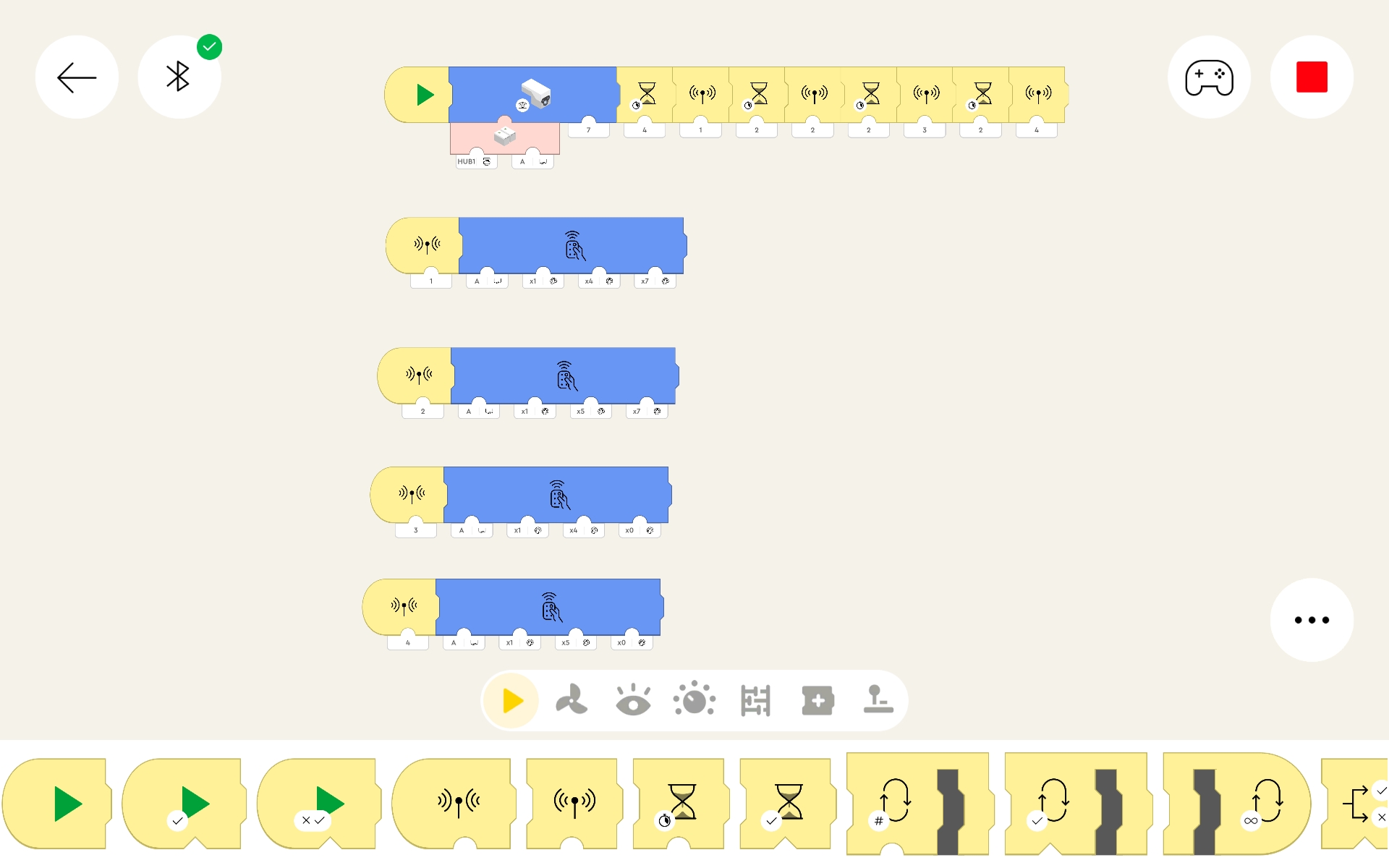
This is intentionally a very simple example. First we set a color/distance sensor to an operation value of 7 (send IR). Then we have a series of delays and calls to subprograms to control lights attached to a Power Function setup. I use the subprograms as an easy way to perform an operation which may be used many times in a more complex project.
Each subprogram sends an IR signal to the Power Functions receiver to set an intensity value for the lights on one of the two (red or blue) connectors. 1 turns on red side lights. 2 turns on blue side lights. 3 turns off red side lights. 4 turns off blue side lights.
If the main code segment was in a loop, the action would keep repeating. It could also be activated by something (remote, sensor value, etc) as a visual indication that something had just occurred.
For me personally, the benefits of PoweredUp being able to control Power Functions are very positive. It allows me to run lights or motors in my code without having to use more ports of the PoweredUp hubs. So by dedicating only 1 PoweredUp hub port and sensor to be used for Power Functions control, I can run a lot of additional accessories using my vast collection of 'outdated' Power Functions units!
Page last updated: June 03 2025 13:53:40.
Page visited: 835
Terrys Place
Book, Motivation speaking, and Bullys
Facebook page
ICIC-ation YouTube channel
Vision and Driver/Bike/Pedestrian safety
Website design
Website programming and utilities:
© 2001-2026 Terry Erickson, All rights reserved.
Website layout and content:
© 2001-2026 Terry Erickson, All rights reserved.
Website hosting:

Proudly made in the USA!